Ruins and archaeological evidence in southern Turkey graphically illustrate several key points
relating to Roman water systems. Aspendos had three consecutive inverted siphons integrated
into its impressive aqueduct system, demonstrating a sophisticated knowledge of hydraulic engineering.
Perge illustrates the Empire's remarkable dependence on high-quality water.
ASPENDOS
To understand the complexity of some of the Roman era aqueducts, a visit to Aspendos is useful.
Aspendos is located 45 kilometers east of modern-day Antalya, in south-central Turkey. Aspendos is
best known for its well-preserved Roman theater. Built in the second century and seating 15,000,
the structure is nearly intact.
Aspendos had its golden age in the 2nd and 3rd century A.D., when it was
an important port and overland trade center. In ancient times, the Eurymedon River, which flows
into the nearby Mediterranean Sea, was navigable as far as the city. Like other cities in antiquity,
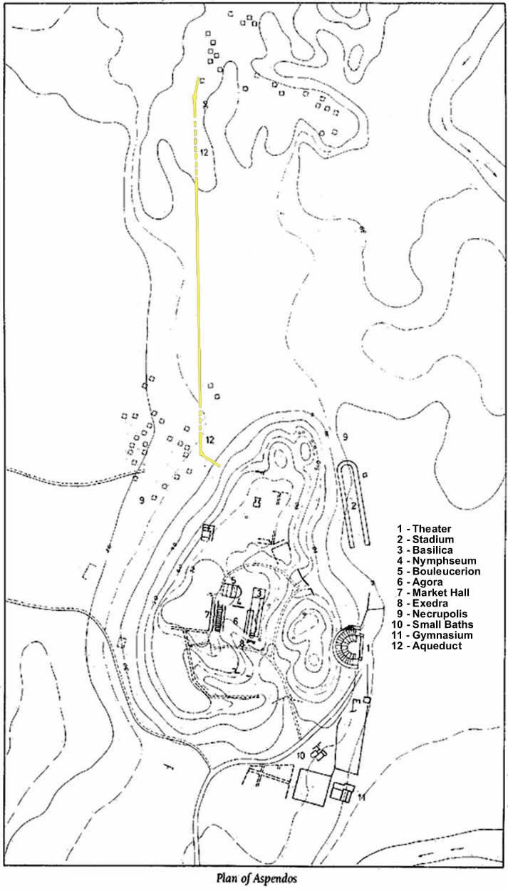
Aspendos was constructed on a hill (for a map of ancient Aspendos see
illustration 1); defense was
an important consideration in the city's development. Early water needs were met by cisterns which
collected rainwater, and by local springs. In time, however, as the population grew and the standard
of living rose, water needs got to point where an aqueduct was needed. And the aqueduct had to bring
water across an adjacent valley to the top of the acropolis.
My two sons and I visited Aspendos in June, 1989. Arriving at the ancient city, we first visited
the theater (see illustration 2) and then walked up to the ruins
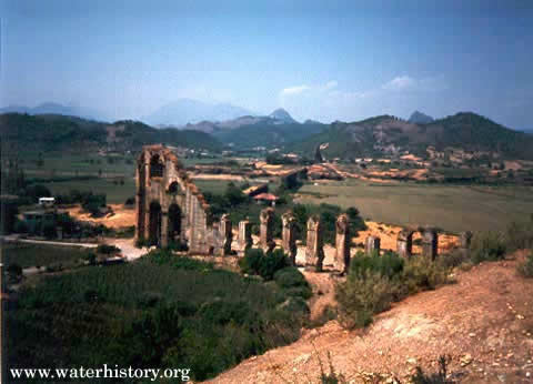
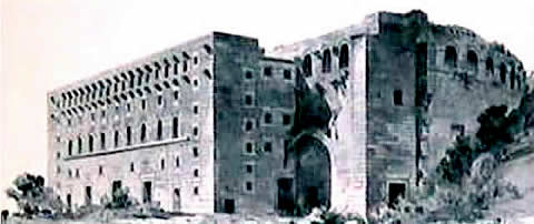
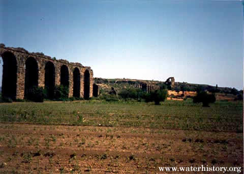
on the acropolis. I was surprised when I saw the remains of the ancient aqueduct (see
illustration 3 and photograph 1).
It is one of the most impressive water conveyance structures remaining from the Roman era.
Illustration 1. Plan of Aspendos.
 | Click on the image for a larger version. |
Water from two sources, located in the mountains 17 kilometers to the north, was carried to within
2 kilometers of the city in a conventional aqueduct channel. The aqueduct is thought to have been
constructed in the first half of the 2nd century. It incorporated several bridges and
tunnels, the channel having modest dimensions, 55-60 cm wide and 90 cm deep on the inside. The
last 1.7 kilometers, between the foothills to the immediate north and the acropolis was a complex
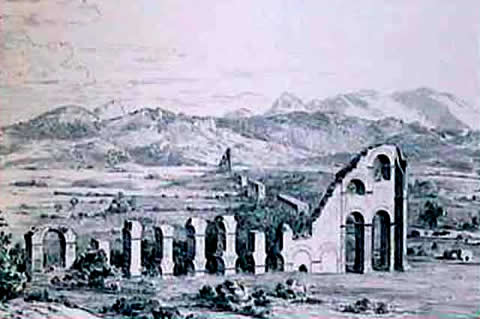
combination of elevated sections and inverted siphons. The most eye-catching structures are two
massive water towers.
From the acropolis, across a small valley or depression, is the first tower (farthest away).
This two-tiered structure bends slightly in the middle to form a 175 degree angle. It is assumed
that the top of the tower was equipped with an open tank. The arches of the tower slope down on
both sides, indicating that the tower held a receiving tank for the first inverted siphon and the
header for the second. (The hydraulic structure is called an inverted siphon because the water
follows the path of a "U" rather than the initially upward course (resembling an "n") of a true siphon.
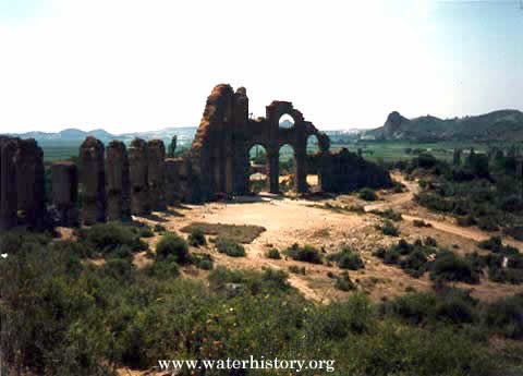
The second siphon, which connects the two towers and stretches over 900 meters on a straight line,
is carried on a row of arches (also called a venter) 15 meters high (see photograph 2). The purpose of the venter was to reduce the head, or the drop from the header tank
to the bottom of the inverted siphon. This section of the aqueduct was 5.5 meters wide leading some to
speculate that it was also used as a roadway when the ground in the valley became marshy.
After crossing the valley, water flowed up to the second tower, which bends to form a 125 degree
angle (see photograph 3). This tower constitutes the transition
between the second and third siphon. It also probably had a tank at the top. From the second tower,
water was conveyed a short distance to the city by a third inverted siphon, again carried on arches.
Each tank on the Aspendos/inverted-siphon system was a little lower than the preceding tank because
friction in the pipes slowed the water, the difference in elevation is the hydraulic gradient.
Today the two towers stand 30 meters above ground level. But during archaeological investigations
in 1996, when the siphons were traced from header tank to receiving tank, it was deduced that the towers
were originally approximately 40 meters high. This would make the Aspendos towers among the highest of
Roman constructions. By comparison, the aqueduct bridge at Pont du Gard
is 48.77 meters in height.
It has been hypothesized that for a valley or canyon crossing under 50 meters deep, Roman engineers
used a bridge alone (Smith, 1978, p. 156; Hodge, 1985, p. 119). For
crossings over 50 meters deep, an inverted siphon was the choice. The depth of crossing at Aspendos is
approximately 55 meters (the towers were 40 meters, plus the venter was 15 meters), just over the
hypothesized 50-meter cutoff.
There is a question of how Roman engineers designed and constructed inverted siphons.
Smith (1978, p. 157) postulates that "the required design was arrived
at empirically." The engineer would build the header tank and pipes first and then would "resort to
judicious trial and error to finally position the receiving tank." For me, this does not seem very
plausible for the structure at Aspendos, one with multiple siphons in series.
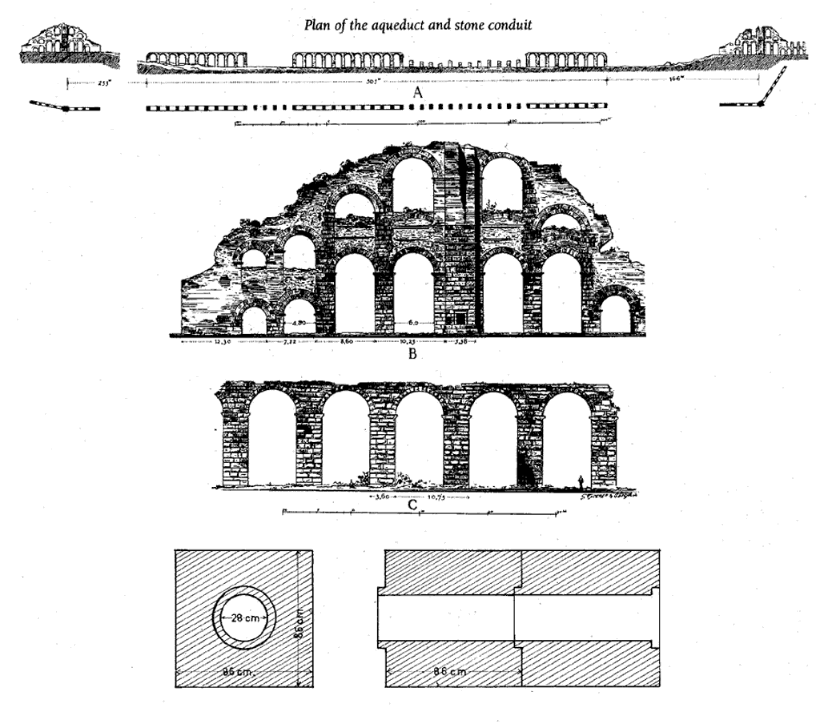
The pipes for the inverted siphon where made of stone. The inside circular diameter was 28-30
centimeters, and the outside was a 86x86x50-90x90x70 centimeter block (see illustration 4). The pipe elements were joined together by means of a socket and flange system and
sealed off by a mixture of lime and olive oil. This latter concoction expands and hardens when in
contact with water and can withstand considerable water pressure. One can still see a few of the
stone-pipe blocks lying along the course of the aqueduct. Originally the three inverted-siphon sections
contained over 3,000 stone-pipe blocks.

Illustration 4. General layout and dimensions of the Aspendos aqueduct.
| Click on the image for a larger version. |
Once the water arrived at the edge of the acropolis, it was carried by means of an open channel
toward the richly decorated Nymphaeum, which stands today on the north side of the agora.
From the Nymphaeum, where the citizens drew water from basins along its front, the water
presumably flowed to the huge cistern on the east side of the agora, and also to both bath complexes,
which are down on the plain to the south of the acropolis.
It has been long known that stone-block pipes from the Aspendos siphons were used in the construction
of a Seljuk-era road bridge over the nearby Eurymedon River. But surprisingly, during recent archaeological
investigations, it was determined that siphon spolia was used in a Roman predecessor to the Seljuk bridge.
As the inside perforations of several of the block pipe used in the bridge had calcareous incrustations,
these stone-block pipes had definitely been used in the aqueduct. Thus the Romans reconstructed their road
bridge after the Aspendos aqueduct had been abandoned.
From the thickness of the calcareous deposits (sinter) in the aqueduct channel found 10 kilometers
north of Aspendos, it was estimated that water flowed in channel for about 130-150 years. Kessenner and
Piras (1998) speculate that the Aspendos siphon may have been destroyed by an earthquake, like the one that
occurred in Cyprus (located 250 kilometers southeast) in 363 AD. Such an earthquake could well have
destroyed the aqueduct including the siphon and its elevated towers, while also ravaging the road bridge
over the Eurymedon. The bridge was important for the east-west trade route along the coast; it was the
only place to cross the fast flowing river. As the Aspendians did not want to lose their trading position,
their most pressing interest was to rebuild the bridge, and the spolia from the aqueduct was certainly
convenient.
If we assume the construction date of the aqueduct to be in the first half of the 2nd
century AD, after which the aqueduct functioned for about 150 years, it seems probable that the Roman
bridge was reconstructed sometime in the early 4th century AD. Later this bridge was again
destroyed, but it served as the foundation for the Seljuk bridge constructed about 900 years later.
PERGE
To understand the Roman Empire's reliance on water, a visit to nearby Perge is particularly
instructive. The ruins of Perge are located 20 kilometers east of the modern city of Antalya. My sons
and I also visited Perge in 1989 and were surprised by what the archaeological evidence indicates about
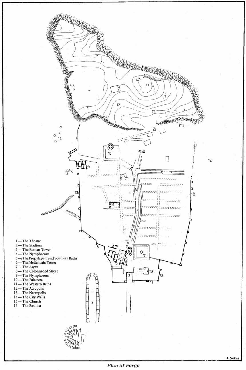
the Roman use of high-quality water (for a map of Perge see illustration 5).
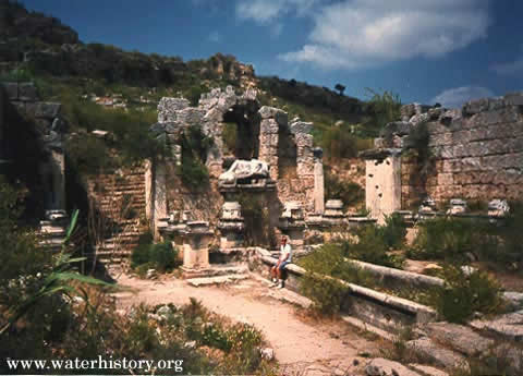
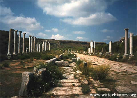
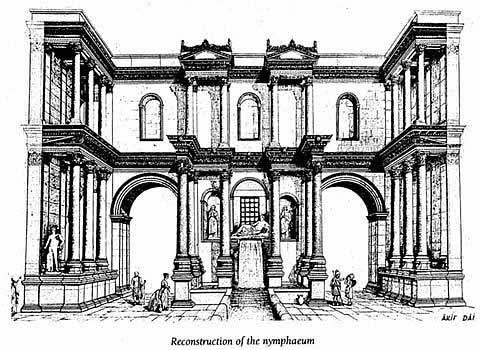
At the southern edge of Perge's acropolis was a monumental fountain (see illustration 6). It is located at the end of a colonnaded street. The fountain was discovered during
excavations in 1970. Water was delivered to a pool located behind the facade via a covered canal. From
this pool water flowed through an opening just below a reclining statue of Cestrus (river god) and into
an exposed, decorative pool (see photograph 4). From here water
overflowed into a canal which divided a colonnaded street.
The city of Perge was surrounded by a wall. And was divided into 4 sections by two intersecting
colonnaded streets. The street running north and south had a 2-meter-wide canal running down its center.
The canal had check structures every 7 to 8 meters to pool the water and facilitate cleaning (see
photograph 5). There were walkways over canal. The sound of water
falling over the barriers must have produced a soothing effect during the hot summers.
Located at the southern end of the colonnaded street was an agora. It was commercial, social, and
political center of the city. The agora was a square surrounded by shops, some opening inward and some
outward to the street. At the center of the agora was a circular water reservoir and fountain. In the
southeast corner of the agora was a latrine. Water ran through the latrine in a continuous flow. It was
connected to Perge's main drainage canal.
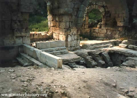
Also at the southern end of the colonnaded street was a large bath. Since most residential units had
no bathing facilities, every Roman city had public baths. Perge's Southern Bath had hot and cold water
and separate bathing areas differentiated by water temperature (see photograph 6).
An underground network of pipes supplied the bath with clean water.
Illustration 5. Plan of Perge.
| Click on the image for a larger version. |
REFERENCES
Atila, I. Akan and Sabri Aydal, unknown, Aspendos and Perge: A Traveler's Guide through Ancient Pamphylian Cities.
(This guide is the source of illustrations 1-4).
Hodge, A. Trevor, 1985, "Siphons in Roman Aqueducts," Scientific American (252:6), pp. 114-119.
Kessenner, Paul and Susanna Pira, 1997, "The Pressure Line of the Aspendos Aqueduct," Adalya II.
Kessenner, Paul and Susanna Piras, 1998, "The Aspendos Aqueduct and the Roman-Seljuk Bridge Across
the Eurymedon," Adalya III.
Smith, Norman, 1978, "Roman Hydraulic Technology," Scientific American (238:5), pp. 154-161.
*Illustrations 2 and 3 courtesy of Suna & Inan KIRAC Research Institute on Mediterranean Civilizations